Overview guide: Relays
This article explains how relays operate. It is a useful reference when installing and troubleshooting relays. Typically, relays can be used on installations that have a PTO, a boom, a dome light, a refrigerated (reefer) truck unit, headlights, a horn, or a door unlock.
In this article:
Relay parts
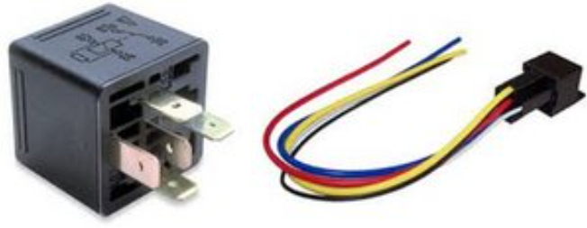
A relay contains parts similar to those of a domestic light switch. However, instead of a switch, relays have mechanical contacts that are electrically closed by the force of a magnetic field that is generated when current passes into a small electromagnet within the relay. For this reason a relay is also called an electromagnetic switch.
We predominantly use Single Pole Double Throw (SPDT) relays. There are many other types of relays, though the parts and basic operation are similar.
The internal parts of a relay comprise of three basic components: contacts, a spring, and a coil.
Contacts
There are three contacts inside a standard relay. They are labelled as follows:
- 87 (see pink arrow in image)
- 87a (see blue arrow in image)
- 30 (see green arrow in image)
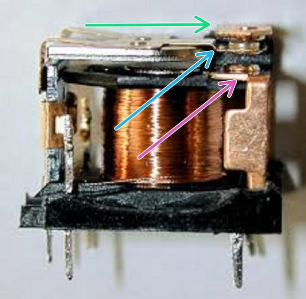
Contact 30 is called “Common” due to its ability to move between contact 87a and contact 87.
Contact 87a is called “Normally Closed” (NC) because it rests on contact 30 when the relay is not energised.
Contact 87 is called “Normally Open” (NO) because it makes no contact with contact 30 until the relay is energised.
Spring
The spring type can vary. The relay is considered to be at rest when the coil is not energised. When the relay is at rest, the spring holds contacts 30 and 87a together. These contacts make an electrical connection while the relay is resting or energised.
Coil
The coil has two connection points; they are labelled 85 and 86 on an SPDT relay. The coil generates a magnetic field when current is passed through it. This magnetic field then causes the common contact or “Pole” (30) to contact the normally open contact (87) and disconnect from the normally closed contact ( 87a). Positive (+) and negative (-) polarity can be supplied to connection points 85 and 86. The connection points can receive either positive or negative polarity unless the relay has a “quenching diode”. If the relay has a “quenching diode”, the connection points in the coil are polarity specific. 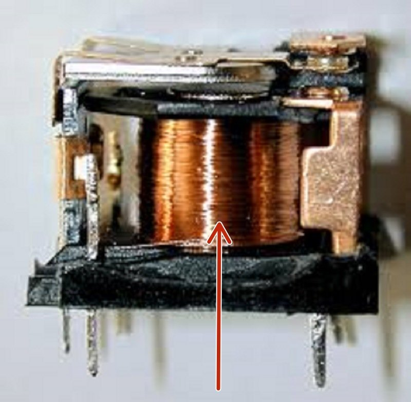
Relay categories of use
A relay has many different configurations that can be classified into four categories of use: amplifying, interrupting, selecting, and inverting.
Amplifying
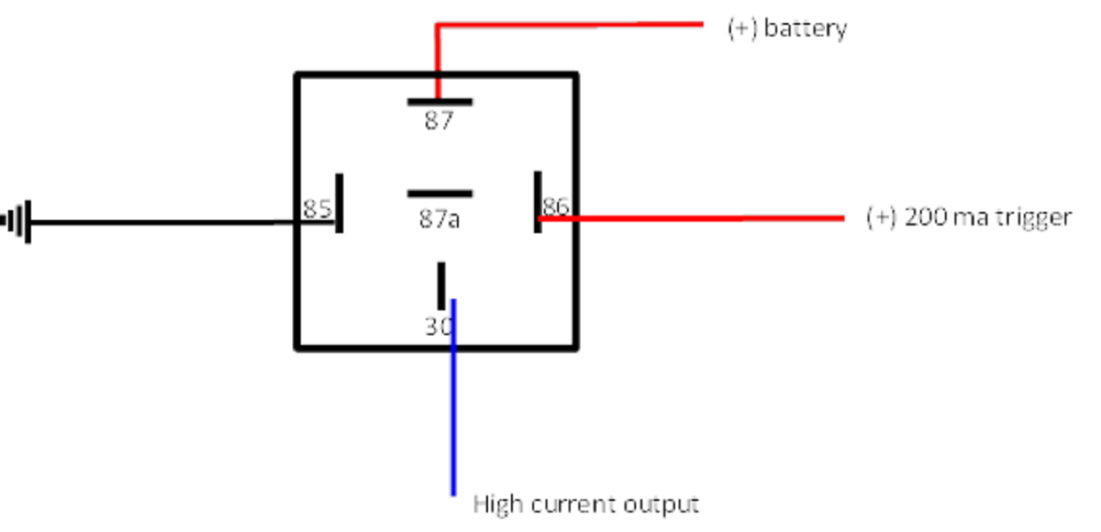
With a relay you can use a small amount of current to pass a larger current. For example, to power windows, headlights, or a starter. The relay diagram below shows a possible 200 mA trigger being used to send a high current (+) out as needed. In this case, contact 87 and contact 30 could be reversed. 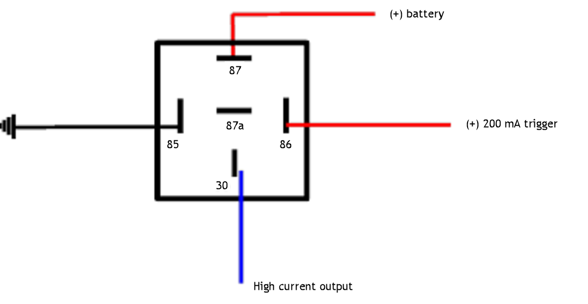
Interrupting
A relay can be used to interrupt a circuit when required. Examples include starter/ignition kill, some door locking circuits, and lighting systems. The relay diagram below shows how you can interrupt a starter circuit with a negative (-) trigger. When the coil is energised it opens the circuit so that the starter wire is disconnected (open circuit) The cut starter wire can be interchanged between contact 87a and contact 30. 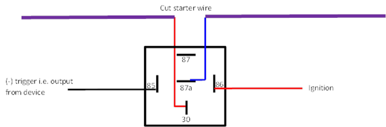
Switching
Relays are used extensively for electrical switching, whereby a relay can be used to switch on and off between two circuits. The diagram below shows switching power between two devices. When the relay is at rest, power is sent to device A. When the relay is energised, power is sent to device B. 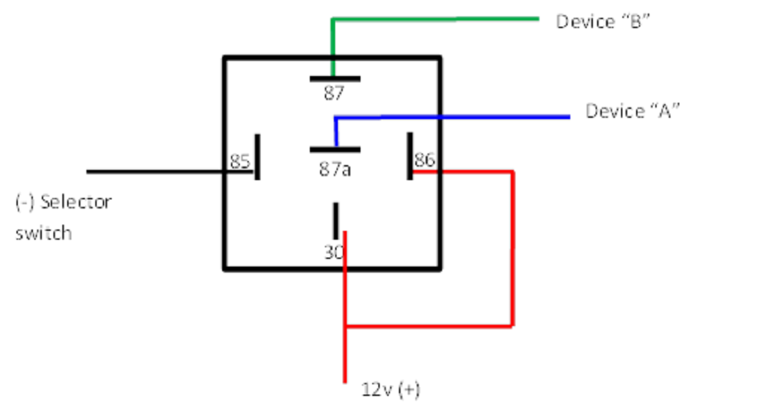
Inverting
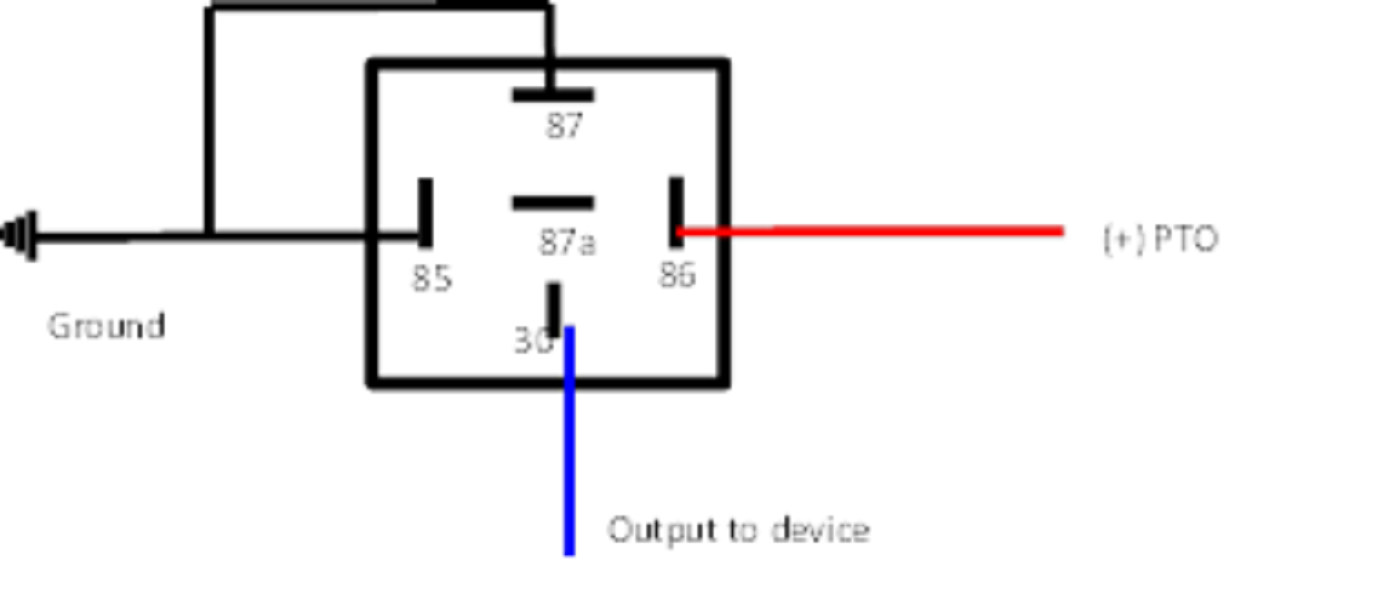
When a circuit is positive (+), and negative (-) is required, you can use a relay to reverse or invert the circuit. For example: on a PTO, a boom, or a dome light.
The diagram below shows using a positive (+) wire to send a negative (-) signal. 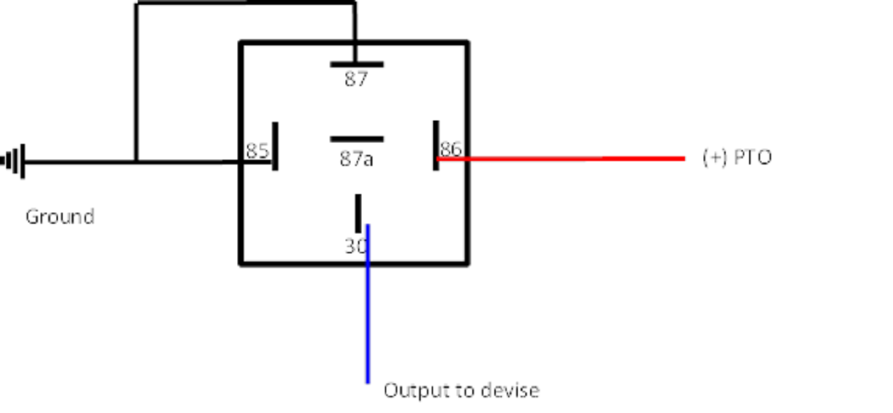
Relay uses
Relays are used for inputs and outputs with our devices.
We typically use relays for inputs when we need:
- To isolate the device from the vehicle, or to isolate one electrical system from a separate electrical system.
- To reverse polarity.
We typically use relays for outputs when we need:
- To drive equipment with high current.
- To interrupt a connection.
Relay inputs: examples
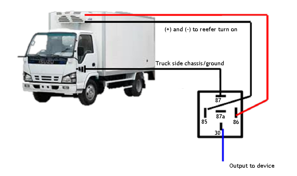
Example 1: to isolate the device from the vehicle, or to isolate one electrical system from a separate electrical system.
A customer has a hybrid refrigerated truck on which the reefer is electrically powered instead of diesel-powered. The reefer runs on a separate electrical system to that of the truck. The two electrical systems cannot be connected together or share a ground. We need to monitor when the reefer turns on/off, but the device we are using has to be installed on the truck's electrical system. We do this by using the reefer to trigger a relay, which sends a ground from the truck side.
Example 2: to reverse polarity
Customer has a truck with a PTO that needs to be monitored. It tests as (+) when on and (0) open when off. Because it shows both open and (+) we may not see it switching states. Because of this we need to reverse the polarity going to the device. We do this by using the (+) when on to trigger a relay sending (-) when on and (0) open when off.
Relay outputs: examples
Example 1: to drive something with high current
When we need to provide a high current supply we use the output from the device to trigger a relay to send the current. Examples include a headlight, a horn, or a door unlock.
Example 2: to interrupt a connection
When we need to break a connection, we use the output from the device to trigger a relay to cut it. An example is starter kill.

PTO examples
PTO example 1
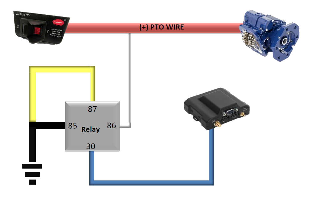
This example shows how to use an SPDT relay for positive (+) PTO. This relay uses the positive (+) PTO signal to activate the relay, sending a ground signal to the device input #1.
(For locations, see device wire diagram.)
PTO example 2
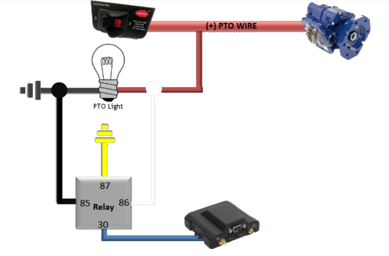
This example shows how to use an SPDT relay for (+) PTO at a PTO light. This relay uses the (+) PTO signal to activate the relay, sending a ground signal to the device input.
PTO example 3
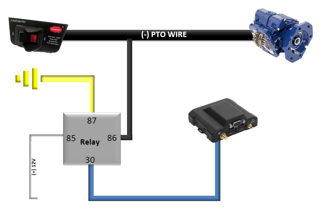
This example shows how to use an SPDT relay for (-) PTO. This will use the (-) PTO signal to activate the relay sending a ground signal to the device input #1.
(For locations, see device wire diagram.)
PTO example 4
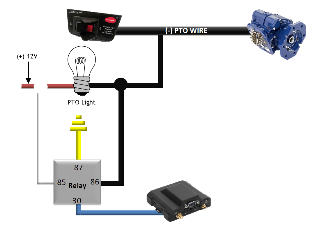
This example shows how to use an SPDT relay for (-) PTO at a PTO light. This relay uses the (-) PTO signal to activate the relay, sending a ground signal to the device input.
Disclaimer
Verizon Connect shall have no liability whatsoever for any damages that arise from, or are connected with, your use of our services, including GPS tracking hardware, in a manner contrary to the(se) instructions or in violation of law and/or our agreement. Installed devices may only be removed and transferred to another vehicle if the second has been tested for compatibility, as per the(se) instructions. Transfers between vehicles which do not follow the(se) instructions will void any and all warranties from Verizon Connect, and relieve Verizon Connect of all liability for damages that arise from or are connected with your use of the devices.