Installation guide: CalAmp TTU 28XX on Reveal
Skill level: Expert
The installer can identify and connect to common engine and electrical systems on vehicles and assets; such as control modules, sensors, trigger wires, alternators, starters, and solenoids. The installer can use pull-up and pull-down resistors, relays, and diodes.
Estimated time for install: 15-30 minutes
This article outlines how to install all CalAmp TTU 28XX series powered asset trackers.
It covers:
Preparing for installation
Before you install the device, there are a few things that you need to do to ensure a smooth installation process.
Check the box contents
You should receive the following:
- CalAmp 28XX
Get your fleet ready
We recommend installing the device outdoors in an area with good network coverage.
Gather your tools and supplies
Depending on your vehicle type, you might need some of the following tools:
- Dash panel removal tools
- Wire stripping tools
- Digital voltmeter
- Cordless drill
- General purpose screwdriver bit set
- Sockets (standard/metric)
- Work light
- Electrical tape - Super 33 grade or better
- Extra zip ties
- Extra self-tapping screws
- Extra heat shrink ring terminals, butt connectors, and a mini-torch
- Add-A-Circuit fuse adapters
Installing the device
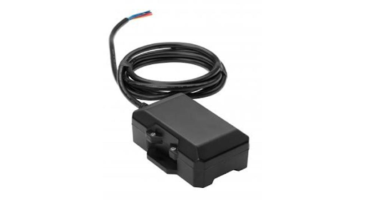
1. Identify parts of the device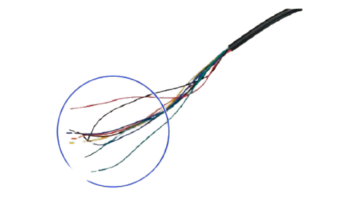
The device has a multi conductor cable with bare ends.
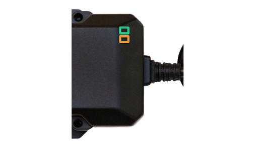
The vehicle tracker is equipped with two Status LEDs, one for GPS and one for COM (wireless network):
- GPS LED (Green)
- COM LED (Amber)
2. Choose where to mount the device
The device must be mounted:
- In an area that’s clear of moving parts.
- With a clear view of the sky.
- Ensure any holes made to pass cable are properly insulated.
- It is recommended to run a bead of silicone at the base of the device when exposed to the elements.
- Do not place directly under metal.
3. Record the device and vehicle information
Record the device Equipment Serial Number. You need this along with the vehicle details, to verify the installation.
The ESN label is on the bottom of the device.
4. Connect the wires of the power harness to the asset's electrical system
DO NOT connect the power harness to the vehicle tracker at this time.
Using the asset tracker with an asset which has an ignition source requires 3 connections: GROUND, IGNITION, and POWER.
Using it with an asset with no ignition source requires only 2: POWER and GROUND. In these cases, you can ignore step 3.
- Connect the ground line wire (black) to the body or frame of the asset, for example the chassis.
- Use a ring terminal to terminate the ground wire to the chassis with a self-tapping screw or a factory bolt.
- Connect the ignition input wire (white) to an ignition source that will only receive power when the ignition is ON.
- Connect the power input wire (red) to a battery source where there is constant power, even when the ignition is OFF.
- Connect directly to the asset battery terminal or as close to it as possible. This connection point should be fuse protected to not more than 5 amps.
To determine a true ignition power source:
- Select a wire.
- With the engine OFF, use a voltmeter to measure the DC voltage on the wire. It should show 0 volts.
- Turn the key to the Accessory position. The voltage should still show 0 volts.
- Turn the key to the On/Run position. The voltmeter should show 12 volts.
- Crank the motor and make sure that the voltage does not drop below 9 volts.
- While the asset is running, confirm that the voltage on the same wire is 12 volts or higher.
- Turn the asset’s engine OFF and confirm that the voltage on the same wire is 0 volts.
Tip: If the voltage does not display as indicated here, you are not testing a true ignition wire.
If the installation requires extending the harness’ ignition wire outside the cab and directly to an alternator or solenoid, protect the wire and connection using a heat shrink ring terminal, dielectric grease, and wire loom along with a weatherproof fuse holder, and fuse of 3-5 amps.
5. Confirm that the asset tracker is connected correctly
Wait for the device to acquire a signal, this can take up to 5 minutes.
Once a signal has been acquired, turn the engine ON for 30 seconds, then OFF. Wait 10 seconds, then repeat this process.
Tip: If the device can't be connected to the vehicle power supply during installation, connect to the orange wire to the ground for 5 seconds. This allows the device to operate for up to 20 minutes, using its own battery.
Check the device’s LEDs.
Green LED (GPS)
- Off = GPS OFF
- Solid = GPS connected
Orange LED (Com)
- Off = Modem OFF
- Solid = Cellular lock
Installing sensors
Temperature Probe
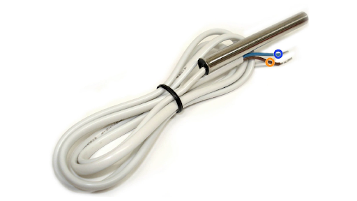
- The temp probe wire (white / blue) should be connected to the blue wire from the probe.
- The brown wire from the probe should be terminated to a ground common to the device.
- The Ignition wire should be terminated to a Refer on/off source.
Digital inputs
- Terminate this wire to the desired input. This could be, PTO, BOOM, REAR DOOR, or a light.
- Inputs should switch between (-) and (+), or (-) and open polarity.
- A relay may be required for installation.
Input wires:
- Blue wire = designated for PTO
- Orange/blue wire = designated for Boom
Verifying operation
Verify that the device is reporting correctly by searching for the vehicle name or the device’s serial number in Reveal.
Learn how to Verify an installation in Reveal.
Installation Partners
Verizon Connect Installation Partners should use the Reveal Hardware Installer (RHI) app to verify the installation. If you experience any issues with the RHI app, contact the Installer Support team.
Disclaimer
Verizon Connect shall have no liability whatsoever for any damages that arise from, or are connected with, your use of our services, including the GPS tracking hardware and dash cams, in a manner contrary to the(se) instructions or in violation of law and/or our agreement. Tracking hardware connected to the diagnostic port in any vehicle that has third-party devices also connected to the diagnostic port can cause interference or loss of functionality of the third-party device. These third-party devices include, but are not limited to, wheelchair lifts, lifesaving equipment, emergency lighting, and radar guns. If such a conflict exists, contact Verizon Connect support to have the tracking hardware configured to support the third-party device. Failure to do so relieves Verizon Connect of all liability for damages that arise from or are connected with your use of the devices. Installed devices may only be removed and transferred to another vehicle if the second vehicle has been tested for compatibility, as per the(se) instructions. Transfers between vehicles which do not follow the(se) instructions will void any and all warranties from Verizon Connect, and relieve Verizon Connect of all liability for damages that arise from or are connected with your use of the devices.