Installation guide: CalAmp 42XX with Y-cable | OBD-II
Skill level: Expert
The installer can identify and connect to common engine and electrical systems on vehicles and assets; such as control modules, sensors, trigger wires, alternators, starters, and solenoids. The installer can use pull-up and pull-down resistors, relays, and diodes.
Estimated time for install: 20-40 minutes
This guide explains how to install a CalAmp 42XX, using a Y-cable, in a vehicle that has an OBD-II port.
A powered Y-cable allows you to conceal the vehicle tracker and to keep the vehicle’s OBD-II port free for diagnostic tool scanning.
In this guide:
- Step 1: Position the vehicle
- Step 2: Gather your tools
- Step 3: Check the kit contents
- Step 4: Identify the parts of the CalAmp 42XX unit
- Step 5: Identify the parts of the serial to Molex lead
- Step 6: Identify the parts of the Y-cable for OBD-II data (including power)
- Step 7: Identify the OBD-II connector and mounting adapters
-
Step 13: Insert the OEM OBD-II connector into the bypass connector (B3)
-
Step 18: Connect the serial to Molex lead to the vehicle tracker
-
Step 19: Connect the accessories cable to the vehicle tracker
-
Step 20: Connect the accessories cable to the vehicle’s electrical system
Step 1: Position the vehicle
Position the vehicle in a location that has good network coverage.
The engine must be off when you are installing the device.
Step 2: Gather your tools
Depending on the vehicle type, you may need the following tools:
- Work light
- Dash panel removal tools
- Driver bits and socket set
- Zip ties
Step 3: Check the kit contents
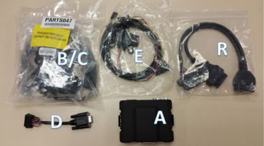
- A: CalAmp 4230 unit with mounting bracket [LMU-4232HE-VRH0- FGEU1 ]
- B: Y-cable for OBD-II data (including power) [PARTS047]
- C: OBD connector and fascia adapters [PARTS04]
- D: Serial to Molex lead NWF-VPOD wiring adapter
- E: Accessories lead [5C420]
- R: Renault-specific Y-cable – This cable and facia connector are specific to vehicles with Renault engines (for example: Opel, Mercedes, Peugeot vehicles, and others not listed) [ZT-BG-117]
Step 4: Identify the parts of the CalAmp 42XX unit
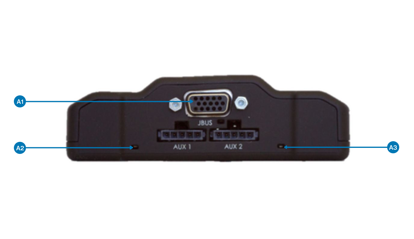
- A1:
- A2: GPS LED (green)
- A3: COM LED (amber)
The device is equipped with two Status LEDs, one for GPS and one for COM (wireless network):
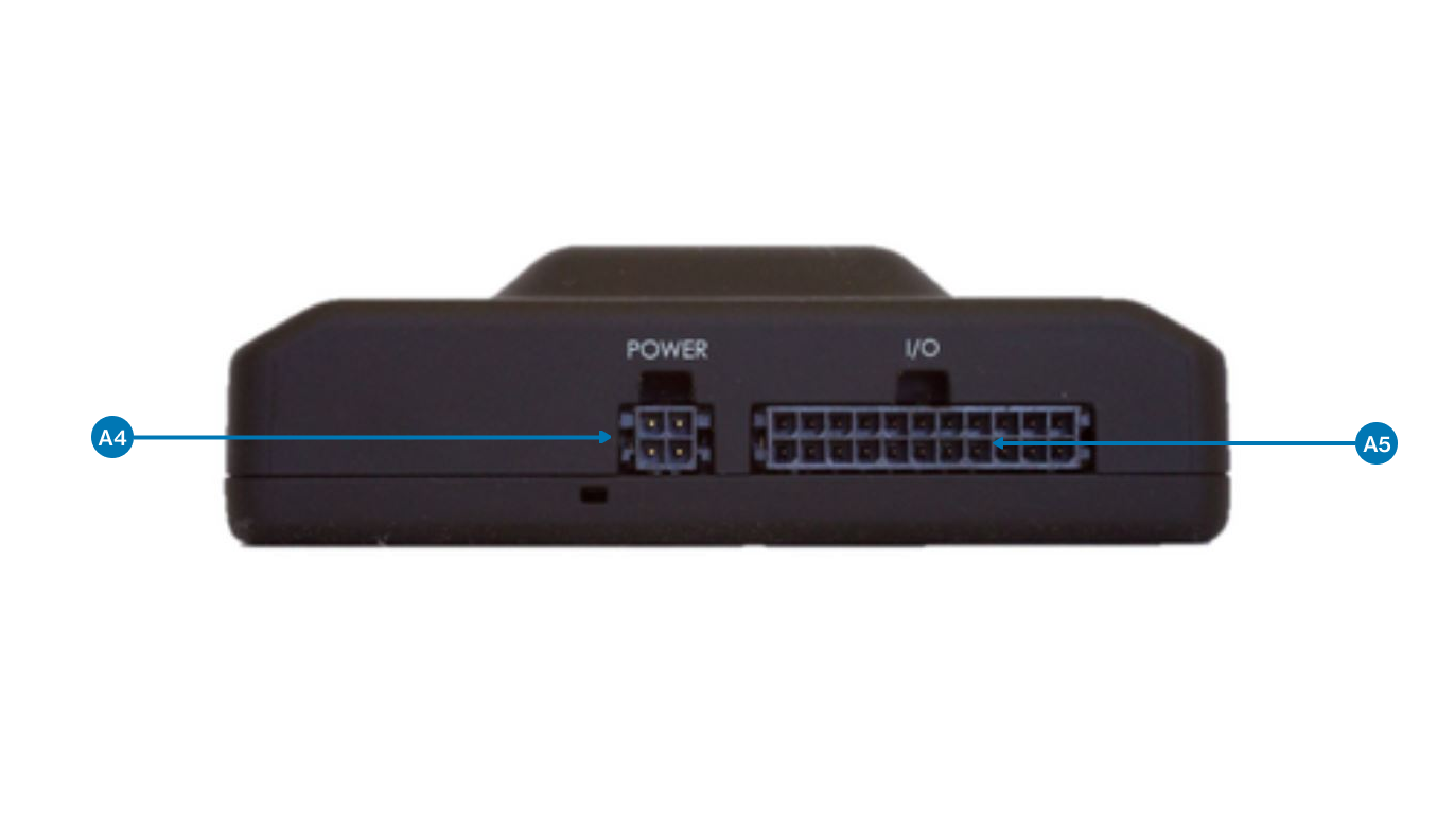
- A4: 4-pin Power harness connection for the 3-wire harness.
- A5: 22-pin I/O connection for accessories
Step 5: Identify the parts of the serial to Molex lead
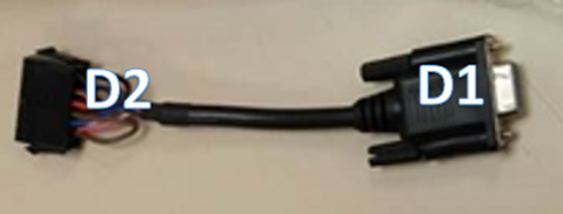
D1: Connects the power to the vehicle tracker loom at A1
D2: Connects to the Y-cable for OBD data lead at B2
Power connections from this lead are taken from the OBD connector and ignition events are created by OBD data so now hard wiring is required for this cable.
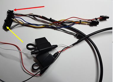
Step 6: Identify the parts of the Y-cable for OBD-II data (including power)
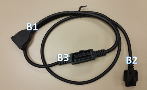
B2: Connects to D2 on Serial to Molex lead
Remove the OEM OBD plug from the vehicle fascia and connect directly to B3
B1: Connect to C1 when C1 has been correctly coupled with an adapter and positioned in the hole vacated by the previously removed OEM OBD port.
Step 7: Identify the OBD-II connector and mounting adapters
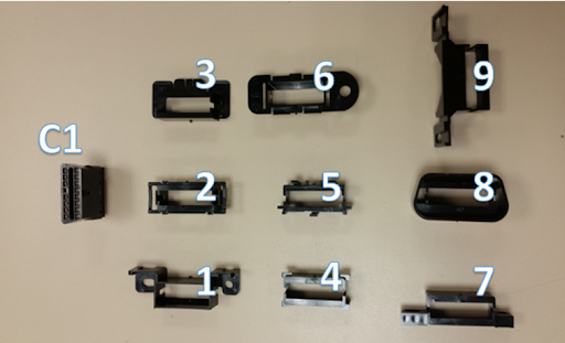
- C1: OBD-II connector
- 1 to 9: Mounting adaptors
Step 8: Identify the parts of the Renault-specific Y-cable
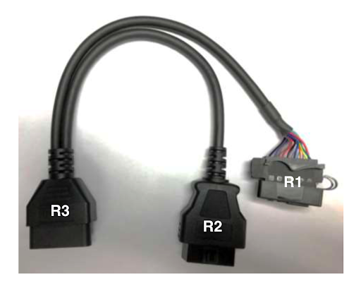
This cable and facia connector are specific to vehicles with Renault ENGINES (so that may include Opel/Mercedes/Peugeot vehicles and others not listed).
For some vehicles with Renault engines, a non-standard OBD connector is present.
In this instance, disregard the instructions for the C connector and use the R cable instead.
- Remove the Renault specific OEM OBD plug from the facia.
- Connect the OEM OBD plug to R2.
- Replace the OEM OBD plug in the facia with R1.
- Connect R3 to B3 on the Y cable (B).
Step 9: Choose where to mount the device
![]()
The device must be mounted:
- Label side down
- Concealed from the driver’s view
- High in the dash for the best signal
- With a clear line of sight out of the vehicle
- Away from heavy metallic surroundings
Never mount the device in the engine compartment, directly on top of the AM/FM radio, by any moving parts, or in a location that would be exposed to the elements.
Step 10: Record the device and vehicle information
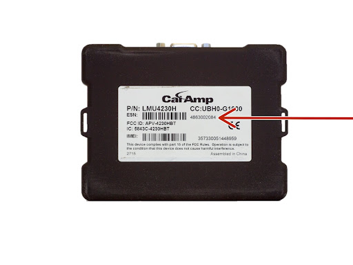
Record the device Equipment Serial Number. You need this along with the vehicle details, to verify the installation.
The ESN label is on the bottom of the device.
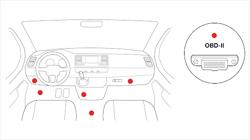
Step 11: Locate the vehicle’s OBD-II port
Locate the vehicle’s OBD-II port by inspecting the following locations (in this order):
- Under the dashboard
- Beneath the steering wheel column
- Each area indicated in the image below
If you cannot locate the vehicle’s OBD-II port, check the vehicle owner’s manual.
Step 12: Unmount the vehicle’s OBD-II port
Remove the vehicle’s OBD-II port from its mounting bracket by pressing the release tabs or by removing the screws that hold it in place. You might need to remove the dash panel to remove the OBD-II port.
Use extreme caution when you unmount the vehicle's OBD-II port. Putting stress on the wires or otherwise damaging the port can cause performance issues with the vehicle.
Step 13: Insert the OEM OBD-II connector into the bypass connector (B3)
- Find the mounting adaptor (1-9) that matches the shape of your vehicle’s OBD-II port.
- Attach the OBD-II connector (C1) to the appropriate mounting adapter.
Step 14: Plug Y-cable into OBD-II connector
To assemble the replacement OBD-II port, plug the Y-cable’s replacement OBD-II connector (B1) into the back of the core connector (C1).
Step 15: Mount replacement OBD-II port
Screw or snap the replacement OBD-II port into the vehicle’s original OBD-II port location.
Step 16: Plug original port into Y-cable
- Plug the vehicle’s original OBD-II port into the Y-cable’s bypass connector (B3).
- Secure the bypass connector to the port with a zip tie.
Step 17: Connect the Y-cable to the serial to Molex lead
Connect the D2 connector of the serial to the Molex lead to connector B2 of the Y-cable.
Step 18: Connect the serial to Molex lead to the vehicle tracker
Connect the D1 connector of the serial to the Molex lead to port A1 on the CalAmp device.
Step 19: Connect the accessories cable to the vehicle tracker
 |
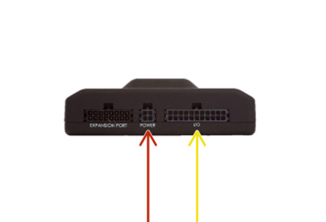 |
- Connect the 4-pin connector on the accessories cable to the power port (A) on the vehicle tracker.
- Connect the 24-pin I/O connector to the to I/O port (B) on the vehicle tracker.
Step 20: Connect the accessories cable to the vehicle’s electrical system
Connect all 3 wires on the power part of the accessories cable to the power source.
- The battery wire (red to a constant power (battery +) source (+30V)
- The ignition wire (white) to an ignition source (+15V)
- The ground wire (black) wire to ground (earth)
Step 21: Connect optional accessories
- Plug required accessories required (Driver ID/ Eco Buzz/ Panic/ Privacy) into the matching Molex sockets on the accessories cable.
- Connect the accessories as described in this guide.
Step 22. Mount and secure the device
Before you mount and secure the device:
- Do not mount the device directly under metal surfaces as this can block the network and GPS signal.
- Do not mount the device near a source of heat such as a heating vent or duct. This can damage the device and melt the cable.
- You must secure the device firmly so it cannot move around. If the device is not secure, it will impact the accuracy of harsh driving events.
- You must coil up and secure the cable so that it does not get in the driver's way or interfere with the driver’s operation of the vehicle.
To mount and secure the device:
- Look for a stable mounting location under the dashboard, such as a wire bundle or bracket.
- Secure the device to the vehicle with zip ties.
- Tidy up the cable and secure it with zip ties.
- Check everything is fastened tightly and cut off excess length of zip ties if needed.
WAIT 10 MINUTES BEFORE SWITCHING THE ENGINE ON. This gives the Vehicle Data Device time to download the latest updates.
Step 23: Verify operation
Verify that the device is reporting correctly by searching for the vehicle name or the device’s serial number in Reveal.
Learn how to Verify an installation in Reveal.
Verizon Connect Installation Partners should use the Reveal Hardware Installer (RHI) app to verify the installation. If you experience any issues with the RHI app, contact the Installer Support team.