Technician guide: Road-facing camera (model 2) using Reveal Hardware Installer app
This guide explains how to install the Road-facing camera (model 2) and is intended for Verizon Connect Installation Partners only.
- Before you begin
-
Installation
- Choose work order
- Scan or enter the camera ESN
- Select the line item for the installation
- Identify the vehicle
- Remove the security cover
- Connect cable A to camera and DC adaptor
- Connect cable B to DC adapter
- Connect the power harnesses
- Boot camera and start firmware update
- Mount the camera
- Adjust and align the camera
- Tidy the cables
- Verify installation
- Troubleshooting
Before you begin
What you should receive
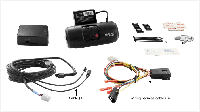
- Camera (x1)
- Alcohol wipes (x2)
- Spare 3M VHB adhesive pad (x1)
- Key (x1)
- Quick start guide (x1)
- Privacy sticker (x1)
- 4 pin to 2.5 mm cable adaptor (x1) - if installing with a road-facing camera (model 1)
Download and sign in to Reveal Hardware Installer app
You must use the Reveal Hardware Installer app to set up the camera.
- Download the Reveal Hardware Installer app.


- Log in to the app with your Verizon Connect credentials.
If you do not have login credentials, contact your administrator.
Important firmware updates
Many cameras have pending over-the-air firmware updates that will automatically download once the camera is connected to power and completes its initial boot sequence.
After the initial boot up, the camera will reboot again twice during the FW update process. After the multiple reboots complete, the camera should be fully operational.
Always let firmware updates complete once they begin. Do not disconnect the camera from power during config updates. Power loss during the update process will corrupt the configuration and cause the camera to malfunction.
Do not swap in an upgraded SD card before the initial device config update completes using the standard SD card. The standard SD card contains important config info. Initial firmware updates must be downloaded and written to the camera using the standard SD card.
If the installation requires an SD card upgrade but the vehicle is not within cell coverage technicians should complete the install WITHOUT performing the SD card swap. Give the larger capacity upgrade SD card to the customer and tell them to drive the vehicle to an area with good coverage so the initial firmware updates can complete.
Advise the customer to only swap the card AFTER the camera's green cell network light becomes solid and to call Support.
Installation
Choose work order
In Reveal Hardware Installer, choose the work order.
Scan or enter the camera ESN
Scan the camera's barcode or select Manual Input, enter the serial number.
Select the line item for the installation
- Select the Dash Camera line item.
- Tap NEXT.
Identify the vehicle
Enter the vehicle identification number (VIN). Alternatively, you can search for the vehicle tracking device ESN or the vehicle license plate, by tapping Change search method.
Remove the security cover
Unlock the camera’s security cover using the provided key and remove it.
Connect cable A to camera and DC adaptor
- Connect cable (A) to the camera.
- Connect cable (A) to the DC power adaptor.
- Make sure the DC power adaptor is switched on.
Connect cable B to DC adapter
Connect the wiring harness (B) to the DC power adaptor.
Connect the power harnesses
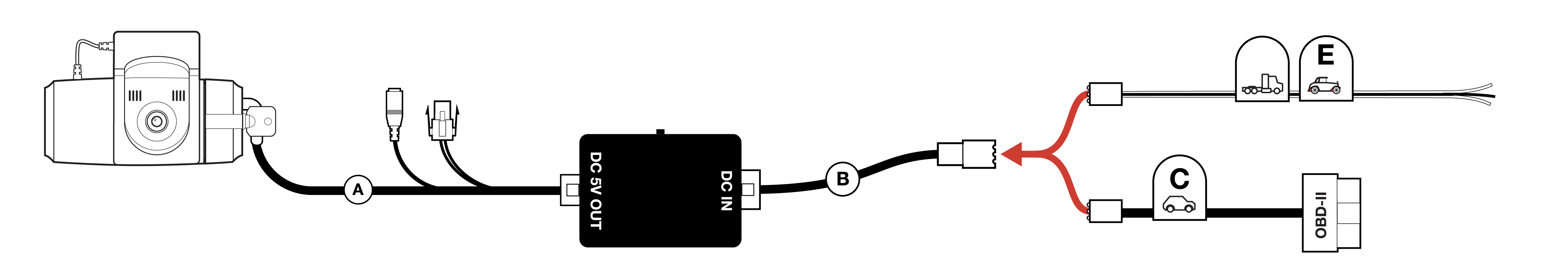
Caution: Before connecting the camera to power, turn the engine OFF, and verify the DC power adapter switch is ON.
For light duty vehicles (12V only), use the OBD-II connector (cable C).
If installing the camera in a vehicle with a Vehicle Data Device installed, you need to use an OBD-II passthrough cable.
For heavy trucks (12V only), light-duty vehicles manufactured before 1996 and heavy trucks with 9 pin connectors, use the 3-wire connector (cable E).
Caution: Use only Verizon Connect approved connection methods when making 3-wire connections. When making ground connections in semi-trucks, be sure to use a factory-marked grounding point or factory-marked spare ground wire. Do not make a standard chassis ground due or splice into another ground wire already in use.
Boot Camera and start firmware update
Booting step 1
On
Off
Off
No sound
Booting step 2
On
On/off
Off
No sound
Booting step 3
On
On
On/off
No sound
Booting finished
On
On
Off
No sound
Camera working normally
Off
On
On
No sound
- Once the camera is connected to power, turn on the vehicle ignition to boot the camera.
- During the boot process, the red, blue, and green lights will flash in sequence.
- Allow the camera to download the latest firmware. This can take a few minutes.
- If the blue and green lights are not solid after 10 minutes, troubleshoot the camera indicator lights.
Mount the camera
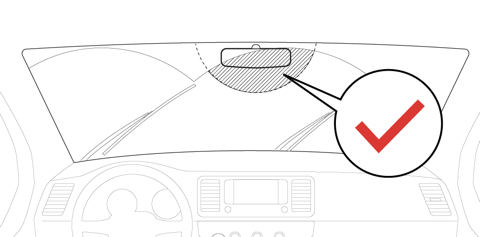
Note: The camera should normally be placed anywhere within the highlighted area. However, customers may choose a mounting location specific to their vehicles configuration and driver needs.
When choosing a mounting location, consider the following:
- The camera should be placed as high as possible within the wiper sweep zone of the windshield on the driver’s side.
- The camera portion of the device should reside in the top 2 inches (5 cm) of the wiper zone.
- The camera must not obstruct the driver's view of the road ahead.
- Avoid placing the camera in the windshield’s dark shaded area around the rear-view mirror - this is where the vehicle's climate control system is. Excess heat can interfere with the camera operation.
- Leave enough space to remove the key from the security cover.
To mount the camera:
- Choose a suitable mounting location for the camera.
- Use the provided alcohol wipes to clean the mounting surface.
Note: Make certain the surface is clean and fully dry before mounting the camera. - Peel off the 3M sticker and attach the camera to the windshield.
- Press the camera to the windshield firmly for 30 seconds.
- Keep the spare sticky pads in case you need to move the camera.
- In the app, choose NEXT.
Adjust and align the camera
- Adjust the camera so that the lens points at the road ahead.
-
In the app, preview the camera image.
- Tap NEXT.
Tidy the cables away
Caution: Do not zip tie the DC converter and vehicle tracker to each other. Doing so may produce EMI which can cause the camera to repeatedly reboot. Secure the DC converter and vehicle tracker at least 6 inches or 150mm apart.
- Route the power cable beneath the headliner, or along it, using the zip tie cord mounts.
Caution: Do not wind the wire harness too tightly. This causes excessive tension and may cause the connection to become unplugged. - Tuck the barrel shaped driver facing camera connector into the headliner, and not placed behind the A-pillar so driver facing camera upgrades are easier to perform.
- In the app, tap NEXT.
Verify installation
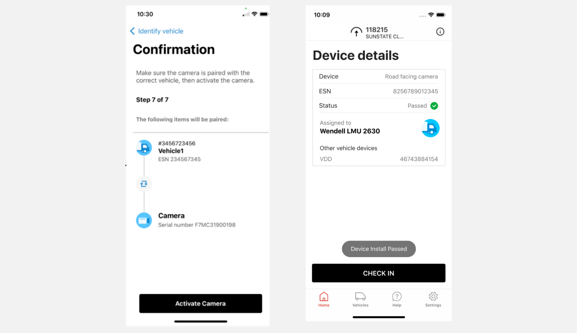
- Confirm that the camera is paired with the correct vehicle, then tap Activate Camera.
- Choose CHECK IN.
Troubleshooting
Note: Verify the DC converter and vehicle tracker are separated by at least 6 inches to prevent electromagnetic interference.
Troubleshooting camera power : input voltage
- Turn on the windshield/windscreen wipers and the defroster/defogger to verify the input voltage does not drop below 13.1V for an OBDII , or below 12V for a 3 wire install.
- Verify the red LED on the output side of the regulator is solid.
- Check ignition between pins 2 and 3, and constant voltage between pins 2 and 8 on the regulator too.
- Verify all Molex pins and wires are snug.
Troubleshooting camera power : output voltage
- The output side of the regulator (going to camera) should shows see greater than ±5V between pin 2 and pins 3-6 when the ignition is on.
- Verify all Molex pins and wires are snug.
Troubleshooting using the camera’s LEDs
Road-facing cameras and driver-facing cameras have three indicator lights to help you identify any issues with its operation:
Red: Warning
Blue: Recording
Green: Network
During normal operation, both the green and blue lights are on.
If the blue light is off and the red light is on or flashing, there could be a problem with the SD card.
If the green light is off or flashing, then there could be a SIM or network error.
Let's look at some common issues.
Rebooting in progress
On
On/Off
Off
No sound
Solution: Turn on the ignition and wait 5 minutes for the camera to boot up. The red, blue, and green lights will flash in sequence.
You will hear a single beep. A single beep indicates your device is plugged in correctly and receiving power. If the blue and green lights are not solid after 10 minutes, contact Support.
If the camera is frequently resetting, followed by a single beep, learn how to stop a camera from continuously rebooting.
Firmware update in progress
Off
On/off twice
On/off twice
No sound
Once the firmware update has finished, you will see:
Off
On
On
No sound
Now reboot your camera by pressing the red button.
Once the camera has rebooted, you can continue camera installation.
Let the firmware update finish before changing the SD card.
If you experience issues, reboot the camera again before contacting Support.
SD error/No SD/Write fail
Slow on/off
Off
On or off
Beep
Solution: Reset the camera. If this does not work, the card may need to be replaced or repaired.
Contact Support.
Network communication error
Fast on/off
On
Slow on/off
Beep
Solution: Check that the camera is within coverage.
3G network device error / SIM error
Off
On
On/off
No sound
Solution: Try the following before contacting Verizon Connect Support:
- Check that the camera is within coverage.
- Reset the camera.
- Turn off the ignition and confirm that the SIM card is installed and with the correct orientation.
Contact Support.
Note: If the installation requires an SD card upgrade but the vehicle is not within cell coverage technicians should complete the install WITHOUT performing the SD card swap. Give the larger capacity upgrade SD card to the customer and tell them to drive the vehicle to an area with good coverage so the initial firmware updates can complete.
Advise the customer to only swap the card AFTER the camera's green cell network light becomes solid and to call Support for assistance with any questions. Reveal Support (866) 908-1165.
Resetting the camera
Press the Calibrate button for three seconds, or until you hear a beep. The calibrate button is the smaller red button on the camera. Use a small tool or paper clip to press the button.