Installation guide: VT-400 light duty vehicles
Skill level: Intermediate
Installers must be able to remove dash panels and instrument clusters, and mount and secure devices safely.
Time required: 15-30 minutes
This article outlines how to install the light-duty VT-400 vehicle tracker.
It covers:
- Preparing for installation
- Installing the device
- Installing sensors
- Mounting the device
- Verifying operation
Preparing for installation
Before you install the device, there are a few things that you need to do to ensure a smooth process.
Check the box contents
You should receive the following:
- VT-400 device
- Diagnostic cable
- VTU connector
- Core connector
- 20 pin connector
- OBD-II bypass connector
- Replacement adaptors
- CIO (optional)
-
Digital input connector (optional)
Get your fleet ready
We recommend installing the device outdoors in an area with good network coverage.
Gather the vehicle information
To complete the setup you need to enter the following information for each vehicle:
- Vehicle name - give the vehicle a name that makes it easily identifiable on Live Map and in reports.
- Vehicle license plate
- Year, make and model of vehicle
- Current odometer reading
Gather your tools and supplies
Depending on your vehicle type, you might need some of the following tools:
- Dash panel removal tools
- Wire stripping tools
- Digital voltmeter
- Cordless drill
- General purpose screwdriver bit set
- Sockets (standard/metric)
- Work light
- Electrical tape - Super 33 grade or better
- Extra zip ties
- Extra self-tapping screws
- Extra heat shrink ring terminals, butt connectors, and a mini-torch
- Add-A-Circuit fuse adaptors
Installing the device
1. Identify the parts
- VT-400
- A - Cable connector
- B - Bypass connector that plugs into the vehicle’s OBD-II port
- C - Fuse holder with replaceable fuse
- D - Device connector for the Vehicle Data Device
- E - Core connector
- F - Mounting adaptors
- CIO (optional)
- Digital Input Connector (optional)
There are CIO and non-CIO specific cables for the VT-400. Please ensure you have the correct cable before installing.
2. Record the serial number
Record the device serial number. You need this along with the vehicle details, to verify the installation.
The serial number is found on the bottom of the device.
We recommend that you record the CIO serial number as well.
3. Choose where to mount the device
The device must be mounted:
- Label side up.
- Concealed from the driver’s view.
- High in the dash for the best signal.
- With a clear line of sight out of the vehicle
- Away from heavy metallic surroundings.
4. Assemble the replacement connector
-
Search the kit provided for the adaptor that matches your OEM diagnostic connector.
-
Insert the core connector into the matching replacement adaptor, aligning the beveled edges, to create the "replacement connector".
- Plug the 20 pin side of the diagnostic cable into the 20 pin side of the replacement connector.
The rubber boot on the cable end can be moved for assembly as needed, but should always be slid back in place.
5. Connect power and replacement connector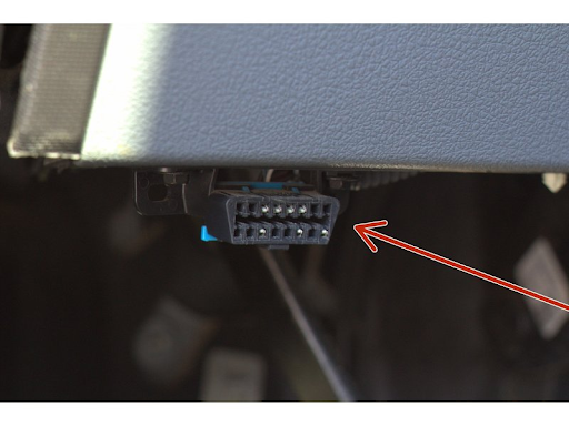
-
Remove the vehicle's OBD-II diagnostic connector from the OEM mount.
- Insert the OEM OBD-II connector into the bypass connector portion of the diagnostic Y-cable to provide power and a diagnostics data feed.
- Re-mount the replacement OBD-II port assembly into the OEM location.
Installing sensors
In order to use digital sensors, you must connect the CIO to the device, then connect the diagnostic cable to the CIO. You can then use the digital input connector to enable sensors:
- Remove the knockout panel and connect the digital input (DI) Molex connector to the CIO. Always start with the first available DI connector location.
- Input position number is left to right.
DI-1 = Input 1 (blue) and Input 2 (purple)
DI-2 = Input 3 (blue) and Input 4 (purple)
It is important to test the voltage signal to ensure it continuously provides the necessary voltage and current in the “on” or “active” position.
-
The signal to be monitored must be capable of supplying 3mA when on and have two voltage states:
- State 1: 0 volts
- State 2: range +5 to +24 volts or -5 to -24 volts
- The following describes how input signals are interpreted.
Wire A - Black or Black striped
Wire B - Solid Blue or Purple
Wire A supplies ground or reference voltage for Wire B which connects to the positive or negative trigger wire of the accessory being monitored.
Ensure that cable placement does not interfere with the driver's operation of the vehicle or with any vehicle controls such as brakes, pedals or steering.
Mounting the device
- Place the provided end cap over the end of the device.
- Due to the internal accelerometer, the device must be secured with zip ties, VHB tape or Velcro. Don’t tape over the ESN on the label (the label will peel and be unreadable when the tape is removed).
-
Secure the device firmly so it cannot move around.
If the device is not secure, it will impact the accuracy of harsh driving events. - Tidy up the cable and secure it with zip ties.
- Check everything is fastened tightly and cut off excess length of zip ties if needed.
Verifying operation
If you’re a Reveal customer, verify your installation in Reveal.
If you’re a professional installer using Reveal, use the Reveal Hardware Installer app.
If you’re installing a device in Fleet, use the Fleet Installer Portal.
Disclaimer
Verizon Connect shall have no liability whatsoever for any damages that arise from, or are connected with, your use of our services, including the GPS tracking hardware and dash cams, in a manner contrary to the(se) instructions or in violation of law and/or our agreement. Tracking hardware connected to the diagnostic port in any vehicle that has third-party devices also connected to the diagnostic port can cause interference or loss of functionality of the third-party device. These third-party devices include, but are not limited to, wheelchair lifts, lifesaving equipment, emergency lighting, and radar guns. If such a conflict exists, contact Verizon Connect support to have the tracking hardware configured to support the third-party device. Failure to do so relieves Verizon Connect of all liability for damages that arise from or are connected with your use of the devices. Installed devices may only be removed and transferred to another vehicle if the second vehicle has been tested for compatibility, as per the(se) instructions. Transfers between vehicles which do not follow the(se) instructions will void any and all warranties from Verizon Connect, and relieve Verizon Connect of all liability for damages that arise from or are connected with your use of the devices.